
cw-manager precheck https://test.com/ – https://test.com
cw-check https://test.com
cw-manager precheck https://test.com/ – https://test.com
ghstbuyer 2807 Mandating this type of extremely important health and fitness benefits guarantees complete coverage for those and you may household, dealing with the diverse health care requires. These types of benefits tend to be emergency characteristics, maternity and you may newborn proper care, psychological state and you can compound fool around with sickness features, prescribed drugs, and a lot more. The marketplace provides multiple choices to be sure medical insurance is accessible and you can affordable to have many anyone.
This web site doesn’t display the offered preparations. † CSRs variations out of Restricted and you will No can also be found for the most other metal level agreements for people in federally approved tribes and you will ANCSA corporation investors. You will find a supplementary premium recharged of these elective benefits.
NTP is a protocol that I find fascinating. Wireless GPS signal to a receiver, and something you can participate online, count me in!
This post is simply focused on the monitoring aspect. For the initial server setup on my Raspberry Pis, I followed a guide from this repo.
I have two pi’s running in my network. I use them as a local time source, but they also participate in the ntppool.org public NTP project. While running them is one thing, monitoring them for jitter/offset and the stratum is important to me that they are working as expected.
To take this further, I decided it was a good time to build a custom Prometheus exporter and start visualizing my own data. You can find the code for this exporter and Grafana dashboard on my own repo.
The python code has several tasks:
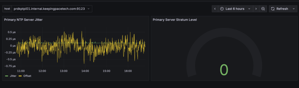
If everything goes well, you will have something like this!
In a future post, I will cover alarming to alert when the stratum level increases above 0 which means the server is not using its own GPS signal for some reason and using another internet time source.
This part of the journey marks over two months of reading my previously linked book, and learning how to setup my own cluster and storage/network components. While I wanted to continue on adding applications I use, like Pihole, Uptime Kuma, and Nextcloud, I thought a first “easy” deployment would be with Librespeed. While I could have run this all in one container, I wanted to explore the micro-service architecture idea and have multiple pods running. Seeing this all finally work was super rewarding!!
While I know I haven’t fully scratched the surface with all the possible Kubernetes components, I tried to take the main concepts that I learned and used them here. I will go over the few that I needed to use. The full Kubernetes MySQL database manifest is posted here, which I reference in sections below.
Remember that container IPs and even containers themselves are stateless. Containers could spin up on one host and get one IP, but it may crash and is recreated on another with a different pod IP space. So, I asked myself, how would my web app have a consistent backend database to send to?
This is where services come into play that will give a consistent IP and DNS name to which other pods can communicate. In my head at least, this operates similar to a load balancer with a front end IP (that stays the same for the duration of the deployment) and a back end which will map to different backend containers. Below is part of the full manifest which I worked through, linked here.
apiVersion: v1
kind: Service
metadata:
  name: mysql
spec:
  ports:
  - port: 3306
  selector:
    app: speedtest-db
This simply tells Kubernetes to create a service named “MySQL” on port 3306, and to choose back ends which have a label of app: speedtest-db. This will make more sense in the Container Definition section.
Config maps have many useful instances. They can be used for environmental variables and, in my case, init configuration commands. As a part of the Librespeed package, a MySQL template is published, which I used to create a table within a database to prepare for data from speed tests to be stored.The challenge was then when the MySQL container first deployed, I needed this template to be applied so upon start the database was ready to go. This was accomplished via config maps and an init.sql definition. I’ll only post part of the config map here, as the full file is in the repository linked above:
---
apiVersion: v1
kind: ConfigMap
metadata:
  name: mysql-initdb-config
data:
  init.sql: |
    use kptspeedtest;
    SET SQL_MODE = "NO_AUTO_VALUE_ON_ZERO";
    SET AUTOCOMMIT = 0;
    START TRANSACTION;
    SET time_zone = "+00:00";
The only addition from Librespeed was to first select the database “kptspeedtest” The rest is just a copy and paste of their template.
In a previous post, I went over my storage setup for persistent storage in Kubernetes. I needed this so when the mysql container is either restarted/moved/deleted etc, the data is still there. The PVC’s job is to request a Persistent Volume for a container from a Storage Class. In my example I already have the SC defined, so I create a PVC for a 20gig storage block:
apiVersion: v1
kind: PersistentVolumeClaim
metadata:
  name: speedtest-db-pvc
  annotations:
    volume.beta.kubernetes.io/storage-class: "freenas-nfs-csi"
spec:
  storageClassName: freenas-nfs-csi
  accessModes:
    - ReadWriteOnce
  resources:
    requests:
storage: 20GiHere is where all the components came together for the pod definition. I’ll step through this as it is a longer manifest:
apiVersion: v1
kind: Pod
metadata:
  name: speedtest-db
  labels:
    app: speedtest-db
Here, I made a pod named “speedtest-db” and applied a label of app: speedtest-db. Remember from the service definition I used the same name? This is how the service knows how to target this container.
spec:
  volumes:
  - name: data
    persistentVolumeClaim:
      claimName: speedtest-db-pvc
  - name: mysql-initdb
    configMap:
      name: mysql-initdb-config
Next under spec.volumes, I first associated the PVC. This references the PVC name above. Then I applied the configMap using the name of the config map here:
 containers:
  - name: speedtest-db
    image: docker.io/mysql:latest
    ports:
    - containerPort: 3306
    env:
    - name: MYSQL_DATABASE
      value: "kptspeedtest"
    - name: MYSQL_USER
      value: "speedtest"
    - name: MYSQL_PASSWORD
      value: "speedtest"
    - name: MYSQL_ROOT_PASSWORD
      value: "speedtest"
    volumeMounts:
      - mountPath: /var/lib/mysql
        name: data
      - name: mysql-initdb
        mountPath: /docker-entrypoint-initdb.d
Then, I gave the definition of the image/ports/environment variables and volumeMounts here. Note, the environment variables you would most likely use are Config Secrets/Config Maps for a more secure/traditional setup.
The volumeMounts are what I used to mount the PV under /var/lib/mysql using the data label, and then provide the initdb config map that was created earlier to prepare the database.
Again, the full manifest is linked here. This example is a Deployment, which is to control the lifecycle/scaling/down scaling of a pod. Technically it’s not needed, but I was throwing in some concepts I had previously learned.
Just like I needed a consistent IP to reach the back end MySQL, I also need a way for consistent and externally accessible entrance into the pods.
apiVersion: v1
kind: Service
metadata:
  name: speedtest-lb
spec:
  type: LoadBalancer
  ports:
  - port: 80
    targetPort: 80
  selector:
    app: speedtest-app
  externalIPs:
  - 192.168.66.251
---
This creates a service of type LoadBalancer, on port 80, and using a defined external IP. This IP then is advertised by Kube Router via BGP to my network to allow routing to the pod. I manually specified this for now, but I hope to add logic in the future to tie into my ipam system and provide next available IP settings.
I will not go over the deployment part of the file, as those concepts I am still testing and learning about.
Onto the container I simply defined the image, a label, and expose it via port 80:
template:
    metadata:
      labels:
        app: speedtest-app
    spec:
      containers:
      - name: speedtest-app
        image: git.internal.keepingpacetech.com/kweevuss/speedtest:latest
        ports:
- containerPort: 80Now it was time to finally give this a go!
Creating the speedtest-db container:
kubectl apply -f speedtest-db-storage-pod.yaml

persistentvolumeclaim/speedtest-db-pvc created
pod/speedtest-db created
configmap/mysql-initdb-config created
service/mysql created
Several components were created: a PVC, the pod itself, a config map, and the mysql service. I verified with some show commands:
kubectl get pvc
NAME STATUS VOLUME CAPACITY ACCESS MODES STORAGECLASS VOLUMEATTRIBUTESCLASS AGE

speedtest-db-pvc Bound pvc-54245a26-9fbe-4a8f-952e-fcdd6a25488b 20Gi RWO freenas-nfs-csi 63s
kubectl get pv | grep Bound
pvc-54245a26-9fbe-4a8f-952e-fcdd6a25488b 20Gi RWO Retain Bound default/speedtest-db-pvc freenas-nfs-csi <unset> 90skubectl get svc
NAME TYPE CLUSTER-IP EXTERNAL-IP PORT(S) AGE
mysql ClusterIP 192.168.100.145 <none> 3306/TCP 115sAbove, I saw what I expected to create. The important piece is that the MySQL service with my instance of a cluster IP of 192.168.100.145
To view the container progress, I ran kubectl get pods to see the container start. One thing I have learned is the init config can take some time to process, which you can see through the logs with kubectl describe or running kubectl logs.
kubectl describe pod speedtest-db

Events:
  Type     Reason                  Age                    From                     Message
  ----     ------                  ----                   ----                     -------
  Warning  FailedScheduling        2m32s (x2 over 2m42s)  default-scheduler        0/4 nodes are available: pod has unbound immediate PersistentVolumeClaims. preemption: 0/4 nodes are available: 4 Preemption is not helpful for scheduling.
  Normal   Scheduled               2m30s                  default-scheduler        Successfully assigned default/speedtest-db to prdkptkubeworker04
  Normal   SuccessfulAttachVolume  2m29s                  attachdetach-controller  AttachVolume.Attach succeeded for volume "pvc-54245a26-9fbe-4a8f-952e-fcdd6a25488b"
  Normal   Pulling                 2m17s                  kubelet                  Pulling image "docker.io/mysql:latest"
  Normal   Pulled                  2m16s                  kubelet                  Successfully pulled image "docker.io/mysql:latest" in 780ms (780ms including waiting). Image size: 601728779 bytes.
  Normal   Created                 2m15s                  kubelet                  Created container speedtest-db
  Normal   Started                 2m15s                  kubelet                  Started container speedtest-db
Through viewing the logs, you can see the different stages of the service. First it will start, but it will eventually stop and run the init commands we passed in via the configMap.
2024-11-04 00:14:47+00:00 [Note] [Entrypoint]: Creating database kptspeedtest
2024-11-04 00:14:47+00:00 [Note] [Entrypoint]: Creating user speedtest
2024-11-04 00:14:47+00:00 [Note] [Entrypoint]: Giving user speedtest access to schema kptspeedtest

2024-11-04 00:14:47+00:00 [Note] [Entrypoint]: /usr/local/bin/docker-entrypoint.sh: running /docker-entrypoint-initdb.d/init.sql
Finally:
2024-11-04 00:14:51+00:00 [Note] [Entrypoint]: MySQL init process done. Ready for start up.

2024-11-04T00:14:58.424295Z 0 [System] [MY-010931] [Server] /usr/sbin/mysqld: ready for connections. Version: '9.1.0'  socket: '/var/run/mysqld/mysqld.sock'  port: 3306  MySQL Community Server - GPL.
I needed to verify that the service is bound to this container:
kubectl describe svc mysql
Name:                     mysql
Namespace:                default
Labels:                   <none>
Annotations:              <none>
Selector:                 app=speedtest-db
Type:                     ClusterIP
IP Family Policy:         SingleStack
IP Families:              IPv4
IP:                       192.168.100.145
IPs:                      192.168.100.145
Port:                     <unset>  3306/TCP
TargetPort:               3306/TCP
Endpoints:                10.200.1.34:3306
Session Affinity:         None
Internal Traffic Policy:  Cluster
Events:                   <none>
Seeing the “Endpoints” filled in, with the IP of this container is a good sign and traffic entering the DNS name of “MySQL” was be sent to the back end endpoint.
I created the web server container:
kubectl apply -f speedtest-deploy.yaml
service/speedtest-lb created
deployment.apps/speedtest-deploy created
It was a little easier with two components, the load balancer and the pod, created.
Now I could go to the load balancers external IP and see it was working!
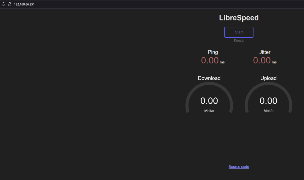
From my router, I saw the external IP was advertised via BGP. But, since my router does not support ECMP in overlay VPRN services, only one is active :(, otherwise it could load balance to any of the three worker nodes’ load balancer services.
*A:KPTPE01# show router 101 bgp routes 192.168.66.251/32
===============================================================================
 BGP Router ID:10.11.0.2        AS:64601       Local AS:64601
===============================================================================
 Legend -
 Status codes  : u - used, s - suppressed, h - history, d - decayed, * - valid
                 l - leaked, x - stale, > - best, b - backup, p - purge
 Origin codes  : i - IGP, e - EGP, ? - incomplete

===============================================================================
BGP IPv4 Routes
===============================================================================
Flag  Network                                            LocalPref   MED
      Nexthop (Router)                                   Path-Id     Label
      As-Path
-------------------------------------------------------------------------------
u*>i  192.168.66.251/32                                  None        None
      192.168.66.171                                     None        -
      65170
*i    192.168.66.251/32                                  None        None
      192.168.66.172                                     None        -
      65170
*i    192.168.66.251/32                                  None        None
      192.168.66.173                                     None        -
65170 Then, I attached to the Kubernetes pod web server to try to connect to the database, and watched as results were loaded. First, I attach to the pod directly:
kubectl exec -it "pod_name" -- /bin/bashMy pod was named speedtest-deploy-6bcbdfc5b7-5b8l5
From the docker image build, I installed mysql-client to try to connect to the database.
mysql -u speedtest -pspeedtest -h mysql


Type 'help;' or '\h' for help. Type '\c' to clear the current input statement.

mysql>
I was in! I simply connected via the login details that were passed in the environment variables of the speedtest database, and used the service name of “mysql” I was able to connect. Just like the web server’s config!
mysql> show databases;
+--------------------+
| Database           |
+--------------------+
| information_schema |
| kptspeedtest       |
| performance_schema |
+--------------------+
3 rows in set (0.04 sec)

mysql> use kptspeedtest;
Reading table information for completion of table and column names
You can turn off this feature to get a quicker startup with -A

Database changed
mysql> show tables;
+------------------------+
| Tables_in_kptspeedtest |
+------------------------+
| speedtest_users        |
+------------------------+

mysql> select * from speedtest_users;
Empty set (0.00 sec)
At this point, I saw the database named “kptspeedtest” with the table created from the MySQL template from Librespeed. Since I had not run any tests yet, there was no data.
After running a speed test, the results are displayed on screen. The idea from the application is you could copy the results URL and send to someone else to view in a browser themselves. When I did the same query I saw data in the database!
mysql> select * from speedtest_users;
+----+---------------------+----------------+------------------------------------------------------------------------+-------+----------------------------------------------------------------------------------+----------------+---------+---------+------+--------+------+
| id | timestamp           | ip             | ispinfo                                                                | extra | ua                                                                               | lang           | dl      | ul      | ping | jitter | log  |
+----+---------------------+----------------+------------------------------------------------------------------------+-------+----------------------------------------------------------------------------------+----------------+---------+---------+------+--------+------+
|  1 | 2024-11-04 00:26:38 | 192.168.66.171 | {"processedString":"10.200.1.1 - private IPv4 access","rawIspInfo":""} |       | Mozilla/5.0 (Windows NT 10.0; Win64; x64; rv:132.0) Gecko/20100101 Firefox/132.0 | en-US,en;q=0.5 | 1198.82 | 1976.27 | 2.00 | 0.88   |      |
+----+---------------------+----------------+------------------------------------------------------------------------+-------+----------------------------------------------------------------------------------+----------------+---------+---------+------+--------+------+
I know it will be hard to read, but you can see id=1, and the client information along with the upload/download/jitter/ping etc.
The first time seeing this work felt like a great accomplishment to get this far. Like I have said through this journey, I know there are enhancements to be made, like Config Secrets. My latest idea of using Init containers to check that the speedtest-db pod is started and the init commands have all run successfully before the web server pod is started.
I hope if you stumbled upon this, you found it useful and that it gave you hope to build your own cluster!
For many years, I have run several containers within my Homelab, such as Uptime Kuma, Librespeed, and Pihole. One thing that always intrigued me was building my own container. Now that I was attempting my first Kubernetes deployment, I thought this would be a good time to understand how to do the process from the beginning.
First, I installed the docker client for my OS. For the desktop OS’s, these are branded Docker Desktop.
Before you create a container image, you must decide where to store it. This is because docker/kubernetes expect images to come from a container registry. For my learning and own development, I use Gitea self-hosted.
There were not really any prerequisites, other than it seemed to be the Gitea instance needed to have https enabled to execute all the docker commands. Myself being lazy and using it locally anyways, I had mine only on HTTP, but this finally got me to have Gitea behind my HAProxy instance to have a valid SSL frontend. Docs for Gitea and container registry are here, and once below the image is built I will show the instructions to push it to the registry.
The docker file is a list of commands/instructions to build the Docker image. It is executed top down, and builds layers to make a full image. Of course, Docker themselves can explain it best.
Fair warning: my example I am sure this is not efficient, nor lightweight but I wanted to try to use something I was at most familiar with to get started. I’m interested as time goes on and my learning grows to better shape these with smaller images, and more efficient commands.
My Dockfile is linked on my personal github. I will step through the important parts:
First I choose to use Ubuntu 22.04 as the base as it is a distribution I am most familiar with.
FROM ubuntu:22.04Next, I refreshed package repositories and then installed the various packages needed for Librespeed to work with a mysql backend. The DEBIAN_FRONTEND=noninteractive instructions php to install non interactivity, as it will ask for a timezone on default install and not let the command ever finish:
RUN apt-get -y update
RUN DEBIAN_FRONTEND=noninteractive apt-get -y install tzdata apache2 curl php php-image-text php-gd git mysql-client inetutils-ping php-mysql
Then from the librespeed package maintainers, there were several configuration changes to be made to PHP, which cloned the package locally:
#Set post max size to 0
RUN sed -i 's/post_max_size = 8M/post_max_size = 0/' /etc/php/8.1/apache2/php.ini

#Enable Extensions
RUN sed -i 's/;extension=gd/extension=gd/' /etc/php/8.1/apache2/php.ini

RUN sed -i 's/;extension=pdo_mysql/extension=pdo_mysql/' /etc/php/8.1/apache2/php.ini

#Prep directory for web root
RUN rm -rf /var/www/html/index.html

#Clone
RUN git clone https://github.com/librespeed/speedtest.git /var/www/html
Next, as I wanted to save results to permanent storage, I changed the telemetry_settings.php file with the various db username/password, db name:
RUN sed -i 's/USERNAME/speedtest/' /var/www/html/results/telemetry_settings.php

RUN sed -i 's/PASSWORD/speedtest/' /var/www/html/results/telemetry_settings.php

RUN sed -i 's/DB_HOSTNAME/mysql/' /var/www/html/results/telemetry_settings.php

RUN sed -i 's/DB_NAME/kptspeedtest/' /var/www/html/results/
telemetry_settings.php
If not clear, my values are: username = speedtest, password = speedtest = dbhostname = mysql (important note here: this is the Kubernetes service name I create later!) and db_name = kptspeedtest.
Skipping some of the basic cleanup/permission settings which you can see in the file, in the end I instructed the container to list on port 80, and to run Apache server as the foreground so the container does not just stop after it is started. There is also a health check for the container to simply see if the Apache service is running.
EXPOSE 80
CMD ["apachectl", "-D", "FOREGROUND"]
HEALTHCHECK --timeout=3s \
CMD curl -f http://localhost/ || exit 1With the file saved as “Dockerfile” I could build the image. First, I logged in to the container registry (in my case my Gitea instance):
docker login git."your_domain_name".comNext, it would normally be as simple as running docker build -t and name of the repo, and image such as:
# build an image with tag
docker build -t {registry}/{owner}/{image}:{tag} .
I ran into some errors with the next step of uploading, and searching around found that adding the flag “–provenance=false” does not include certain metadata about the build and makes it compatible with Gitea. Depending on the container registry, it may or may not be needed. Full example:
docker build -t git."domain_name"/kweevuss/speedtest:latest . --provenance=falseSince the file is named Dockerfile, docker build tried to find that file in the directory. My user is “kweevuss” and this image is being called speedtest and using the “latest” tag.
Then I pushed the image to the registry:
docker push git.internal.keepingpacetech.com/kweevuss/speedtest:latestWithin Gitea then, I could see the image related to my user:
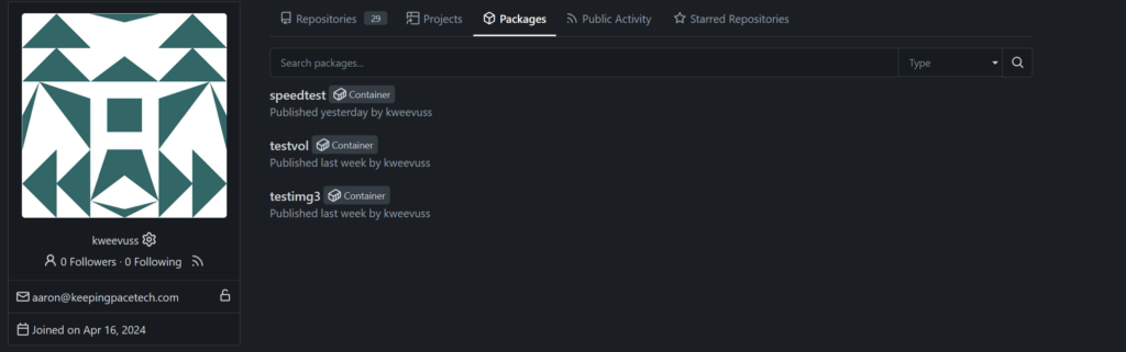
Now on any docker install, I simply pulled the image as:
docker pull git.internal.keepingpacetech.com/kweevuss/speedtest:latestOr, instead, in a kubernetes deployment/pod manifest simply point to the image:
spec:
  containers:
  - name: prdkptspeedtestkube
    image: git."domain_name"/kweevuss/speedtest:latest
Next installment will finally be setting up this custom image along with another container, mysql, to store the data!
In this installment, I will be going over how I set up my external storage to Kubernetes for persistent storage. As with any container platform, the containers are meant to be stateless and do not store data inside the container. So if there is persistent data needed, it needs to be stored externally.
As mentioned in my first post, my book of reference to learn Kubernetes did touch on storage, but does limit it to cloud providers. Which wasn’t as helpful for me, because, of course, in the spirit of Homelab we want to self-host! Luckily there are some great projects out there that we can utilize!
I use TrueNAS core for my bulk data and VM-based iSCSI storage. I was pleasantly surprised to find that TrueNAS does support Container Storage Interface (CSI), so I cover this method below.
I found this great project, democratic-csi. The readme has great steps and examples using TrueNAS, so I will not duplicate here for the sake of simply re-writing the documentation. I am personally using NFS for storage as it seemed more straight forward and with iSCSI it for my back end of all my VM storage from Proxmox. I would rather not modify that config extensively to risk that setup for such an import piece of the lab.
First, I configured TrueNAS with the necessary SSH/API and NFS settings and ran the helm install:
helm upgrade --install --create-namespace --values freenas-nfs.yaml --namespace democratic-csi zfs-nfs democratic-csi/democratic-csiMy example freenas-nfs.yaml file is below:
csiDriver:
  name: "org.democratic-csi.nfs"

storageClasses:
- name: freenas-nfs-csi
  defaultClass: false
  reclaimPolicy: Retain
  volumeBindingMode: Immediate
  allowVolumeExpansion: true
  parameters:
    fsType: nfs

  mountOptions:
  - noatime
  - nfsvers=4
  secrets:
    provisioner-secret:
    controller-publish-secret:
    node-stage-secret:
    node-publish-secret:
    controller-expand-secret:

driver:
  config:
    driver: freenas-nfs
    instance_id:
    httpConnection:
      protocol: http
      host: 192.168.19.3
      port: 80
      # This is the API key that we generated previously
      apiKey: 1-KEY HERE
      username: k8stg
      allowInsecure: true
      apiVersion: 2
    sshConnection:
      host: 192.168.19.3
      port: 22
      username: root
      # This is the SSH key that we generated for passwordless authentication
      privateKey: |
        -----BEGIN OPENSSH PRIVATE KEY-----
        KEY HERE
        -----END OPENSSH PRIVATE KEY-----
    zfs:
      # Make sure to use the storage pool that was created previously
      datasetParentName: ZFS_POOL/k8-hdd-storage/vols
      detachedSnapshotsDatasetParentName: ZFS_POOL/k8-hdd-storage/snaps
      datasetEnableQuotas: true
      datasetEnableReservation: false
      datasetPermissionsMode: "0777"
      datasetPermissionsUser: root
      datasetPermissionsGroup: wheel
    nfs:
      shareHost: 192.168.19.3
      shareAlldirs: false
      shareAllowedHosts: []
      shareAllowedNetworks: []
      shareMaprootUser: root
      shareMaprootGroup: wheel
      shareMapallUser: ""
      shareMapallGroup: ""
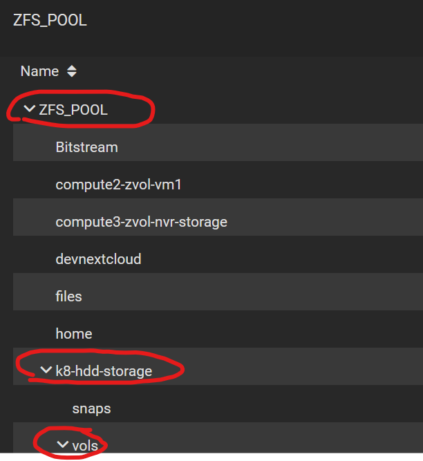
The above file, I felt, is very well-documented from the package maintainers. I had to input API/SSH keys, and the import piece is the dataset information:
datasetParentName: ZFS_POOL/k8-hdd-storage/vols AND
detachedSnapshotsDatasetParentName: ZFS_POOL/k8-hdd-storage/snaps
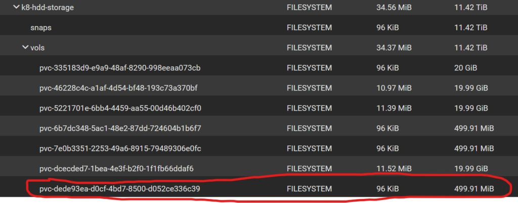
This was dependent on what I had setup in TrueNAS. My pool that looks like this:
With the helm command run, I saw a “Storage Class” created in Kubernetes:

The name comes from the yaml file above. The Kubernetes Storage class is the foundation, and its job is to help automate the storage setup from containers that request storage. These all have specific names like Persistent Volume Claims and Persistent Volumes, which I will get to. The Storage class essentially uses a CSI plugin (which is API) to talk to external storage systems to provision storage automatically. This way Kubernetes has a consistent way to create storage no matter the platform. It could be Azure/AWS/TrueNAS etc.
Now, to get to the interesting part: we can first create a “Persistent Volume Claim” (PVC). The PVC’s job is to organize requests to create new Persistent Volumes on Storage classes. This will hopefully help with an example:
cat create_pvc.yaml
apiVersion: v1
kind: PersistentVolumeClaim
metadata:
  name: nfs-pvc-test
  annotations:
    volume.beta.kubernetes.io/storage-class: "freenas-nfs-csi"
spec:
  storageClassName: freenas-nfs-test
  accessModes:
    - ReadWriteOnce
  resources:
    requests:
      storage: 500Mi
The above yaml file is essentially asking for 500Mb of storage from the storage class named “freenas-nfs-test”
I applied this with the normal “kubectl apply -f create_pvc.yaml”
With this applied, I saw it created, and once completed it was in a bound state:

Now to use this:
cat test-pv.yaml
apiVersion: v1
kind: Pod
metadata:
  name: volpod
spec:
  volumes:
  - name: data
    persistentVolumeClaim:
      claimName: nfs-pvc-test
  containers:
  - name: ubuntu-ctr
    image: ubuntu:latest
    command:
    - /bin/bash
    - "-c"
    - "sleep 60m"
    volumeMounts:
    - mountPath: /data
      name: data
In this pod, I referenced to create a volume with spec.volumes using the PVC name I created in the last step. Then under spec.containers.volumeMounts I give a mount directory inside the container to this directory.
In TrueNAS, at this point, I saw a volume created in the dataset that matches the volume ID displayed in Kubernetes
Attach to the pod:
kubectl exec -it volpod -- bashInside the container now, I navigated to the /data directory and created a test file:
root@volpod:/# cd /data/
root@volpod:/data# ls
root@volpod:/data# touch test.txt
root@volpod:/data# ls -l
total 1
-rw-r--r-- 1 root root 0 Nov  3 04:11 test.txt
Just to see this work in action, now SSHing into the TrueNAS server and browsing to the dataset, we can see the file!
freenas# pwd
/mnt/ZFS_POOL/k8-hdd-storage/vols/pvc-dede93ea-d0cf-4bd7-8500-d052ce336c39
freenas# ls -l
total 1
-rw-r--r--  1 root  wheel  0 Nov  3 00:11 test.txt
In the next installment, I will go over how I created my container images. My initial idea was to use Librespeed and a second container with mysql for results persistent storage. So having the above completed gives a starting point for any persistent data storage needs!
In this first part, my goal is to piece together the bits and pieces of documentation I found for the cluster setup and networking.
A must-read is the official documentation. I thought it was great, but be prepared for a lot reading. It’s not a one-command install by any means. I’m sure there are a lot of sources on how to automate this turn up – which is what all the big cloud providers do for you – but I wasn’t interested in that, so that won’t be covered in these Kubernetes posts.
I ran into two confusing topics on my first install of Kubernetes: the Container Runtime Environment (CRE) and the network plugin install. I will mostly cover the network plugin install below in case it helps others.
First I started out using my automated VM builds (you can find that post here) to build four Ubuntu 22.04 VMs: one controller and three worker nodes.
As you’ll see if you dive into the prerequisites for kubeadm, you have to install a container runtime. I will blame the first failure I had when I tried containerd on just not knowing what I was doing, but on my second attempt I tried Docker Engine, and this did work with success. With the instructions from Kubernetes, I was able to follow without issue.
Once the Kubernetes instructions were followed for the container runtime, the Kubernetes packages could be installed on the control node:
sudo apt-get install -y kubelet kubeadm kubectlNow it’s time to bootstrap the cluster. If you’re using this post as a step-by-step guide, I would suggest coming back once the install and cluster is up to read up more on what kube-init does as it is intriguing.
kubeadm init --pod-network-cidr 10.200.0.0/16 --cri-socket unix:///var/run/cri-dockerd.sock

--service-cidr 192.168.100.0/22
Dissecting what is above:
At the end of this init process, it gave me a kubeadm join command, which is a token and other info to be able to join from the worker nodes to the controller.
kubeadm join 192.168.66.165:6443 --token <token> --discovery-token-ca-cert-hash <cert>--cri-socket unix:///var/run/cri-dockerdAt this point, running kubectl get pods showed the worker nodes, but none were ready until there was a network plugin running and configured.
I tried several network plugin projects, and ended up landing on Kube-router. This really seemed to give my end goal of being able to advertise different services or pods via BGP into my network.
I used this example yaml file from the project page and only had to make slight modifications to define the router to peer to.
For the container “kube-router” in the spec.args section, I defined the peer router ips, and ASN information. For example:
 containers:
      - name: kube-router
        image: docker.io/cloudnativelabs/kube-router
        imagePullPolicy: Always
        args:
        - --run-router=true
        - --run-firewall=true
        - --run-service-proxy=true
        - --bgp-graceful-restart=true
        - --kubeconfig=/var/lib/kube-router/kubeconfig
        - --advertise-cluster-ip=true
        - --advertise-external-ip=true
        - --cluster-asn=65170
        - --peer-router-ips=192.168.66.129
        - --peer-router-asns=64601
I made sure to adjust these settings to fit my environment. You can decide if you want cluster IPs and external IPs advertised. I did enable those but with more understanding, I only envision needing external IPs for load balancer services for example to be advertised.
I ran the deployment with:
kubectl apply -f "path_to_yaml_file"After this, I saw several containers being made:

I saw the above containers will all be running, and when I looked at the route table I saw installed routes to the pod network cidrs to each host:
ip route
default via 192.168.66.129 dev eth0 proto static
10.200.1.0/24 via 192.168.66.171 dev eth0 proto 17
10.200.2.0/24 via 192.168.66.172 dev eth0 proto 17
10.200.3.0/24 via 192.168.66.173 dev eth0 proto 17
172.17.0.0/16 dev docker0 proto kernel scope link src 172.17.0.1 linkdown
192.168.66.128/25 dev eth0 proto kernel scope link src 192.168.66.170
Check out the kube-routers documentation for more info, but essentially the kube router containers formed BGP peers by listening to worker nodes join the pool, and creating routes so pods on different worker nodes can communicate.
I also noticed coredns containers should start, and “kubectl get nodes” showed all the nodes in a ready state:
kubectl get nodes
NAME                  STATUS   ROLES           AGE   VERSION
prdkptkubecontrol02   Ready    control-plane   16d   v1.31.1
prdkptkubeworker04    Ready    <none>          16d   v1.31.1
prdkptkubeworker05    Ready    <none>          16d   v1.31.1
prdkptkubeworker06    Ready    <none>          16d   v1.31.1
At this point I had a working Kubernetes cluster!
In this post, I want to document my learning from knowing nothing to deploying a multi-node Kubernetes cluster that is currently running a Librespeed test server with a mysql back end.
A recent product release from Nokia, Event Driven Automation (EDA), which is based around many concepts of Kubernetes for network automation, piqued my interest in exploring Kubernetes itself. As the tool does not require any Kubernetes knowledge (although the software does run on a K8s cluster), I wondered if it was beneficial. In short, my purpose in learning about Kubernetes was to understand the design physiology and how to support the deployment of EDA.
Disclaimer: I am a network engineer, not a dev ops master so I only slightly know what I’m doing in this space and I know I have a lot to learn to be more efficient, but maybe others just entering into the space can find some ideas in my journey.
I would not be where I am today without The Kubernetes Book: 2024 Edition by Nigel Poulton. I thought it was a very great introduction and explanation of the concepts. The only thing it didn’t cover that I wanted was setting up a Kubernetes cluster from scratch, but the Kubernetes official documentation helped where it lacked.
The following parts are listed below, where I try to go from 0 to a deployed Kubernetes cluster, all self-hosted in my homelab!
In my last post, I went over the configuration of Proxmox, Vyos, and SROS. Here I want to show over how the setup looks and works with real VMs attached to this.
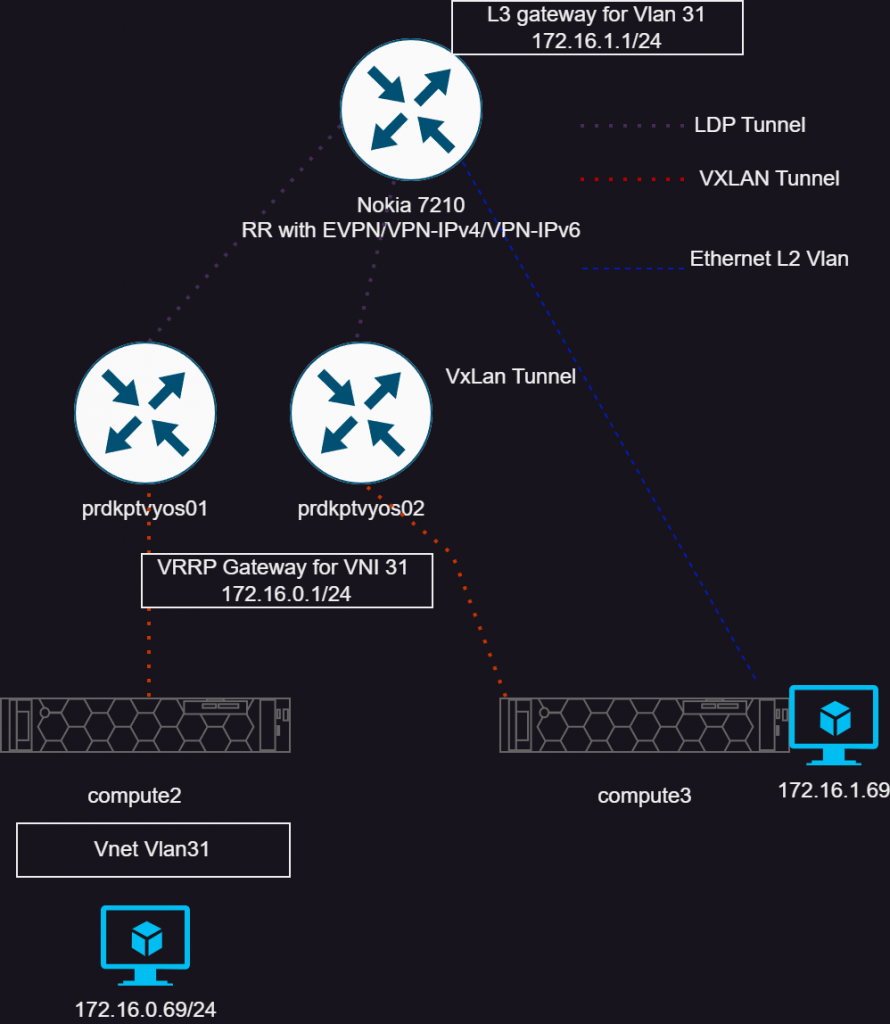
Above I have tried to show the topology. The VM in the bottom left is running on compute2 (Proxmox hypervisor), and attached to the VNET “Vlan31” which has the IP of 172.16.0.69. This VM’s gateway exists on the pair of Vyos instances, which tie the VXLAN tunnel into a VRF. The other VM, 172.16.1.69, is attached to a normal Proxmox bridge/vlan that is routed on the 7210 within the VPRN service. So these VMs are just to show connectivity between these systems.
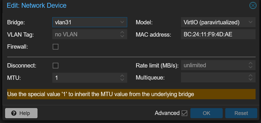
With the Vnet configured in Proxmox, it is possible to assign that to a VM’s interface. Which simply looks like this below:
The other VM, I’m simply using a traditional linux bridge, and a vlan.
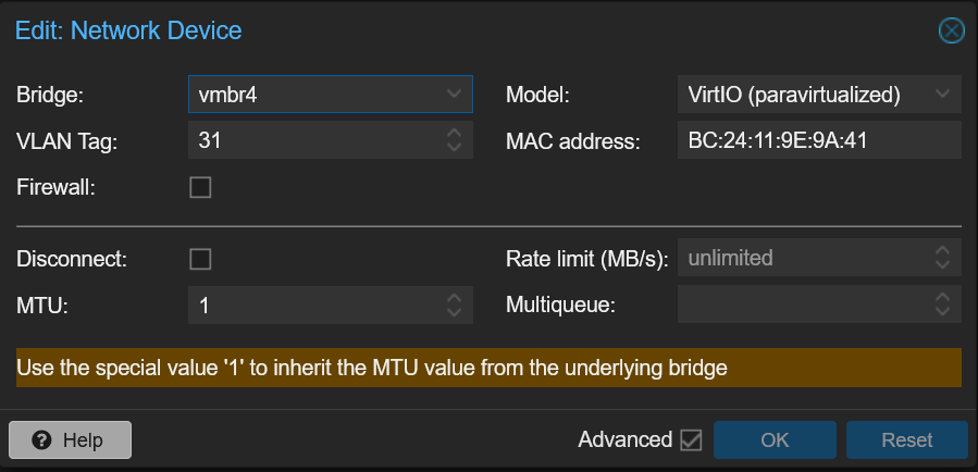
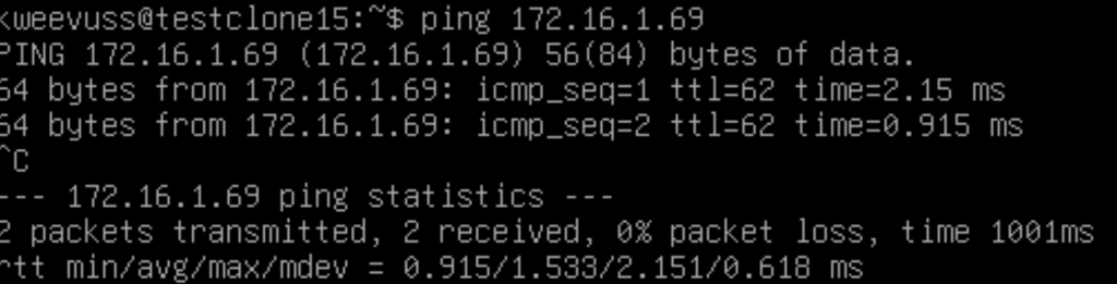
The VM above is the 172.16.0.69 VM, and showing connectivity to the other VM on 1.69. Let’s dive in how it works.
First I will lay out the IPs and macs for reference.
| 172.16.0.69 (testclone15) | BC:24:11:F9:4D:AE |
| 172.16.1.69 (testclone16) | BC:24:11:9E:9A:41 |
First we can look at the EVPN type 2 route (mac address) for the first host.
A:KPTPE01# show router bgp routes evpn mac mac-address BC:24:11:F9:4D:AE
===============================================================================
 BGP Router ID:10.11.0.2        AS:65000       Local AS:65000
===============================================================================
 Legend -
 Status codes  : u - used, s - suppressed, h - history, d - decayed, * - valid
                 l - leaked, x - stale, > - best, b - backup, p - purge
 Origin codes  : i - IGP, e - EGP, ? - incomplete

===============================================================================
BGP EVPN MAC Routes
===============================================================================
Flag  Route Dist.         MacAddr           ESI
      Tag                 Mac Mobility      Ip Address
                                            NextHop
                                            Label1
-------------------------------------------------------------------------------
*>i   192.168.254.18:2    bc:24:11:f9:4d:ae ESI-0
      0                   Seq:0             N/A
                                            192.168.254.18
                                            VNI 31
And we see it as we expect on the SROS router. We have the mac address, the VNI it’s attached to and the next hop which will be the interface on compute2 (Proxmox hypervisor).
vyos@devkptvyos02:~$ show evpn mac vni all

VNI 31 #MACs (local and remote) 4

Flags: N=sync-neighs, I=local-inactive, P=peer-active, X=peer-proxy
MAC               Type   Flags Intf/Remote ES/VTEP            VLAN  Seq #'s
d0:99:d5:5a:c8:ec remote       192.168.254.137                      0/0
ea:89:3c:f0:86:82 local        br1                            1     0/0
86:a8:39:b4:ec:43 remote       192.168.254.137                      0/0
bc:24:11:f9:4d:ae remote       192.168.254.18                       0/0
Then on Vyos, we can see the mac address of the VM is learned. This is because SROS is sending the EVPN route to the Vyos instances, and it installs it in it’s table. The gateway which is 172.16.0.1 that exists within our vrf called “test-vprn” has a mac of ea:89:3c:f0:86:82
Now the packet will route to the gateway, and Vyos will look in it’s route table on how to get to 172.16.1.0/24.
vyos@devkptvyos02:~$ show ip route vrf test-vprn
Codes: K - kernel route, C - connected, S - static, R - RIP,
       O - OSPF, I - IS-IS, B - BGP, E - EIGRP, N - NHRP,
       T - Table, v - VNC, V - VNC-Direct, A - Babel, F - PBR,
       f - OpenFabric,
       > - selected route, * - FIB route, q - queued, r - rejected, b - backup
       t - trapped, o - offload failure

VRF test-vprn:
C>* 172.16.0.0/24 is directly connected, br1, 6d12h41m
B>  172.16.1.0/24 [200/0] via 10.11.0.2 (vrf default) (recursive), label 131056, weight 1, 01:48:05
  *                         via 10.0.0.8, eth1.34 (vrf default), label 131071/131056, weight 1, 01:48:05
Now Vyos has a route using a MPLS transport and service label to the SROS router.
Lastly on the Nokia router, it will simply deliver it over vlan 31.
A:KPTPE01# show router 231 route-table

===============================================================================
Route Table (Service: 231)
===============================================================================
Dest Prefix[Flags]                            Type    Proto     Age        Pref
      Next Hop[Interface Name]                                    Metric
-------------------------------------------------------------------------------
172.16.0.0/24                                 Remote  BGP VPN   01h54m38s  170
       10.11.0.140 (tunneled)                                       0
172.16.1.0/24                                 Local   Local     11d08h37m  0
       vlan31                                                       0
-------------------------------------------------------------------------------
No. of Routes: 3
Flags: n = Number of times nexthop is repeated
       B = BGP backup route available
       L = LFA nexthop available
       S = Sticky ECMP requested
===============================================================================
A:KPTPE01#
At this point, we can see some of what the traffic looks like on the network. I am capturing from “compute2” for anything with the port 4789 for VXLAN.
tcpdump -i any port 4789
13:43:29.824872 enp4s0 Out IP 192.168.254.18.53966 > 192.168.254.140.4789: VXLAN, flags I, vni 31
IP 172.16.0.69 > 172.16.1.69: ICMP echo request, id 3, seq 9, length 64 <– Inner
13:43:30.827019 enp4s0 In IP 192.168.254.140.52047 > 192.168.254.18.4789: VXLAN, flags I, vni 31
IP 172.16.1.69 > 172.16.0.69: ICMP echo reply, id 3, seq 10, length 64 <– Inner
So we can see the VM 172.16.0.69 sending a ping request to 172.16.1.69. That packet is encapsulated in VXLAN, and send from the Proxmox IP to Vyos. We also see the return, also encapsulated in VXLAN.
So of course, doing this all with two hosts in a single network isn’t all that useful per say. But imagine having many hosts, and even those hosts not being in the same area, that can support being on the same L2 network and mobility. Although stretching L2 across WANs is not always the best idea, but I’ll leave that up to your discretion 🙂
With Proxmox 8, and production support of software defined networking, I started to take a harder look at what is possible.
From my understanding, this feature is built on FRR. In this blog, I am looking to take an unconventional approach at using this. From the Proxmox documentation, most of what this feature seems to be used for is networking nodes together which could be over a WAN etc. There are limited options that are available in the GUI, which of course is all you need for this feature to work. I wanted to see what was happening under the hood, and expand on this by having networking features outside of just the hosts too.
Ideally, my setup would consist of VXLAN tunnels terminating on a router, where I have a layer 3 gateway within a VRF. Problem is, while the 7210 supports EVPN, it only supports transport over EVPN-MPLS. Most every opensource project that I have found only supports VXLAN. So my idea was then to use Vyos in the middle, which can terminate the VXLAN tunnels from the Proxmox nodes, and then route from a VRF, to another VRF on the 7210 via MPLS.
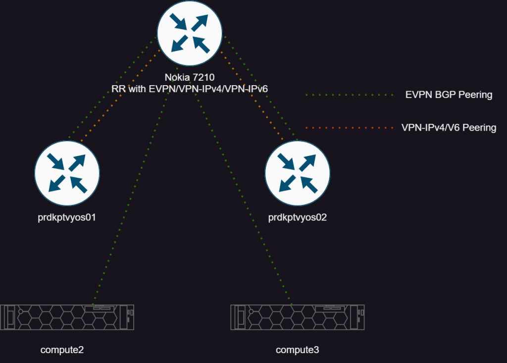
The first picture I’m depicting the control plane of this setup. I am using a Nokia 7210 as a route reflector with several different address families. EVPN for the Proxmox nodes, and EVPN/VPN-IPv4/v6 towards Vyos. More on VPN-IPv6 though, as sadly ran into some unresolved issues.
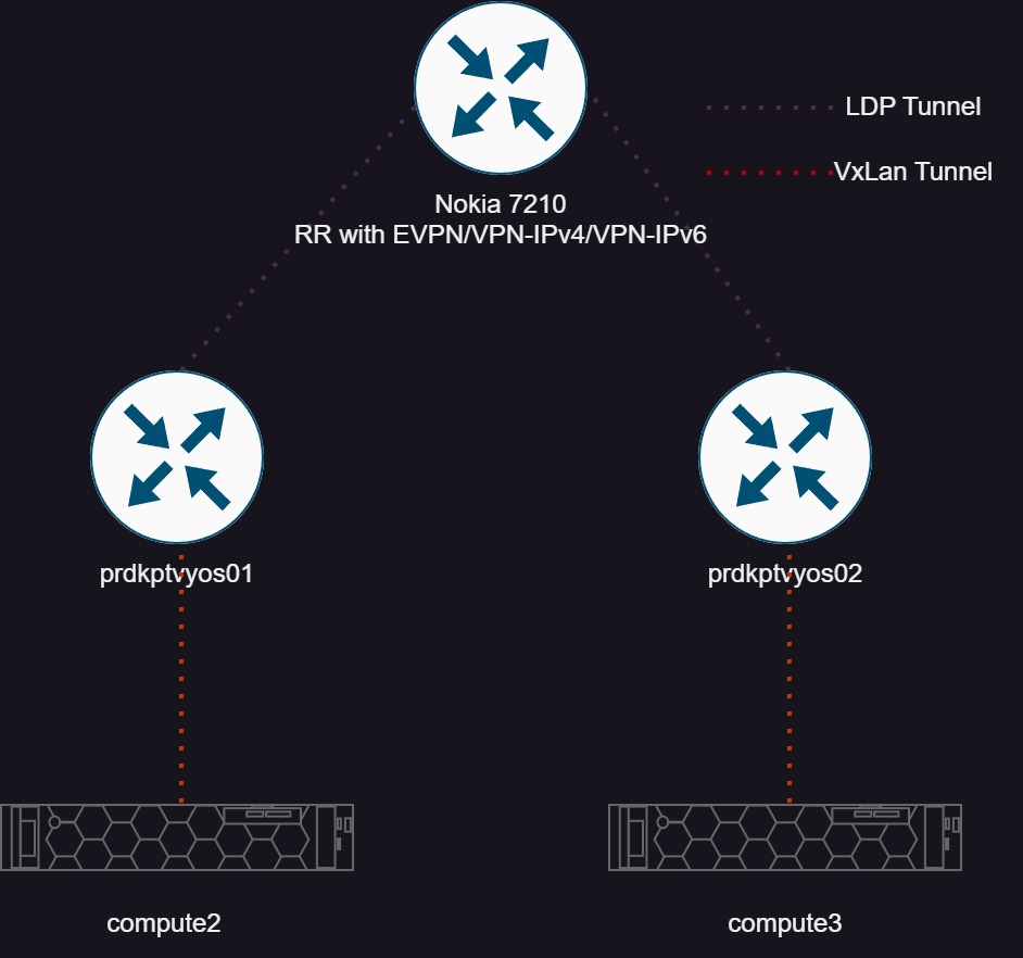
The second pictures shows the transport tunnels. Simply, VXLAN from Proxmox to Vyos ( It would be full mesh, I neglected to draw it here) and LDP tunnels to the 7210.
There are some prerequisites that are all covered in the Proxmox documentation in chapter 12. All of these settings are under Datacenter >SDN. First let’s setup a “controller” which is really just defining an external router which will run the EVPN protocol. Under options, add a EVPN controller.
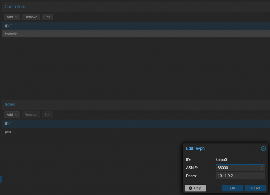
Here simply give it a name, ASN, and peer IP. Then on my router config, I defined a peer group and a cluster id, which means this peer group will act as a route reflector:
A:KPTPE01>config>router>bgp# info
----------------------------------------------

            group "iBGP-RR"
                family ipv4 vpn-ipv4 evpn
                cluster 10.11.0.2
                peer-as 65000
                advertise-inactive
                bfd-enable
                neighbor 192.168.254.13
                    description "compute3"
                exit
                neighbor 192.168.254.18
                    description "compute2"
                exit
            exit
If all goes well, then the peer should come up:
192.168.254.13
compute3
                65000  138929    0 04d19h46m 1/0/35 (Evpn)
                       139268    0
192.168.254.18
compute2
                65000  138099    0 04d19h04m 1/0/35 (Evpn)
                       138432    0
Next, need to define a zone. Proxmox gives this as a definition of “A zone defines a virtually separated network. Zones are restricted to specific nodes and assigned permissions, in order to restrict users to a certain zone and its contained VNets.” In my case, I’m using this to define the vxlan tunnel, and it’s endpoints, which end up being my two vyos instances.
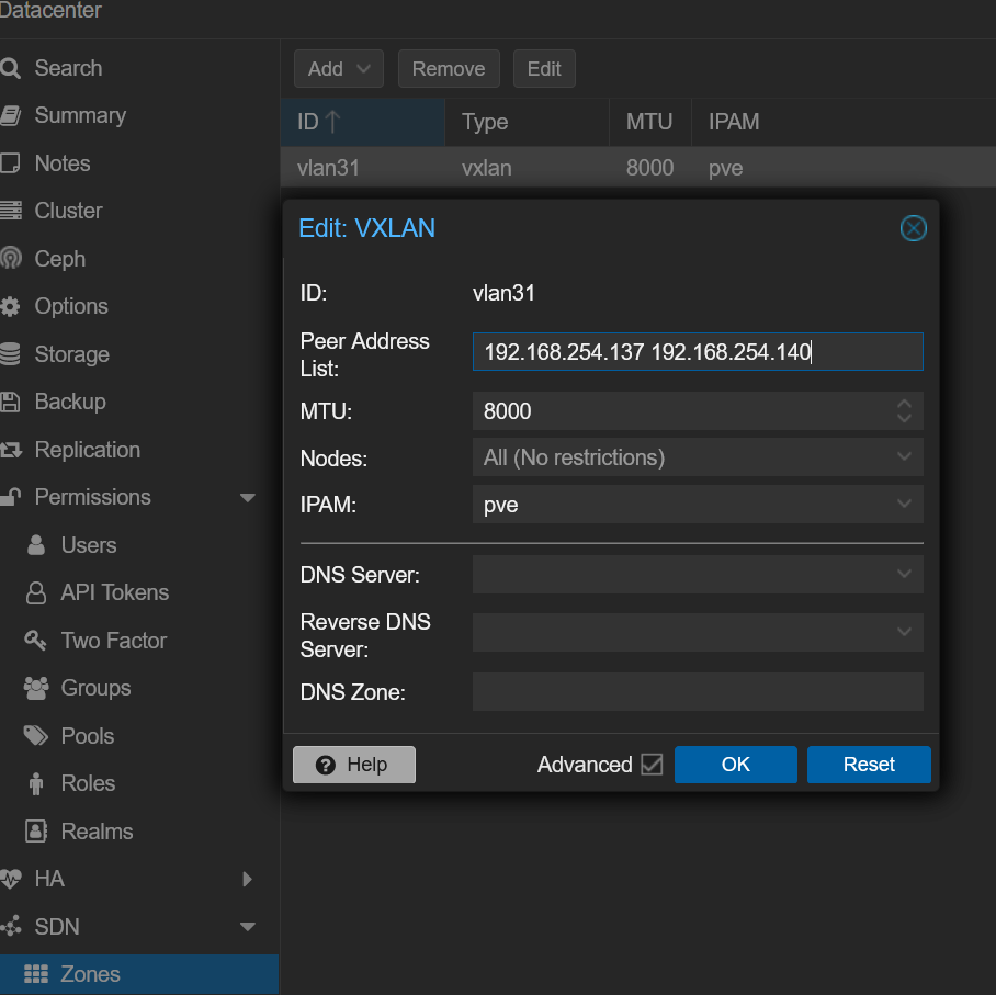
Last thing is to create a vnet. The vnet will be what VMs are actually attached to, and to create a broadcast domain. This config is simple, basically tying together a zone and give it a name a tag, which the tag ends up being the VNI.
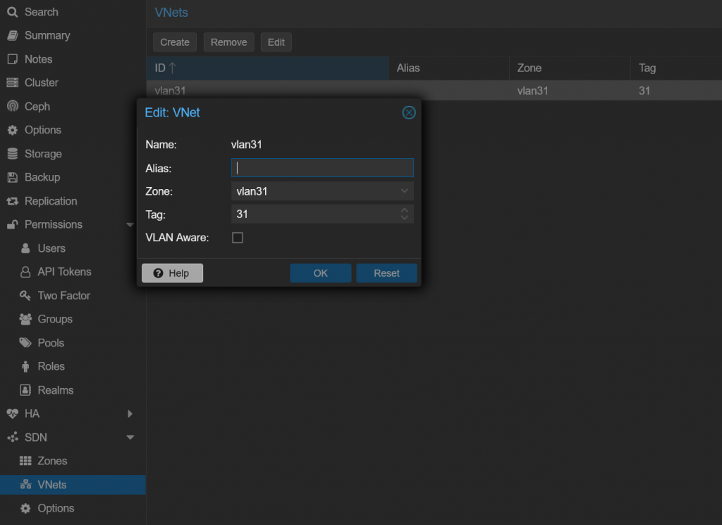
Looking on the Nokia, we can look at what the include multicast routes. As a quick overview, inclusive multicast routes are what are advertised between routers to announce the service. If two peers have RTs and a VNI match, they can build a VXLAN tunnel and exchange data.
A:KPTPE01# show router bgp routes evpn inclusive-mcast rd 192.168.254.18:2 hunt
===============================================================================
 BGP Router ID:10.11.0.2        AS:65000       Local AS:65000
===============================================================================
 Legend -
 Status codes  : u - used, s - suppressed, h - history, d - decayed, * - valid
                 l - leaked, x - stale, > - best, b - backup, p - purge
 Origin codes  : i - IGP, e - EGP, ? - incomplete

===============================================================================
BGP EVPN Inclusive-Mcast Routes
===============================================================================
-------------------------------------------------------------------------------
RIB In Entries
-------------------------------------------------------------------------------
Network        : N/A
Nexthop        : 192.168.254.18
From           : 192.168.254.18
Res. Nexthop   : 192.168.254.18
Local Pref.    : 100                    Interface Name : vlan1
Aggregator AS  : None                   Aggregator     : None
Atomic Aggr.   : Not Atomic             MED            : None
AIGP Metric    : None
Connector      : None
Community      : bgp-tunnel-encap:VXLAN target:65000:31
Cluster        : No Cluster Members
Originator Id  : None                   Peer Router Id : 192.168.254.18
Flags          : Valid  Best  IGP
Route Source   : Internal
AS-Path        : No As-Path
EVPN type      : INCL-MCAST
ESI            : N/A
Tag            : 0
Originator IP  : 192.168.254.18         Route Dist.    : 192.168.254.18:2
Route Tag      : 0
Neighbor-AS    : N/A
Orig Validation: N/A
Add Paths Send : Default
Last Modified  : 04d19h19m
-------------------------------------------------------------------------------
PMSI Tunnel Attribute :
Tunnel-type    : Ingress Replication    Flags          : Leaf not required
MPLS Label     : VNI 31
Tunnel-Endpoint: 192.168.254.18
First we can see from the communities, the encapsulation is VXLAN, and the route target. Also then the VNI, which is the tag we picked as in “31” in this case. If this router supported vxlan, we would be good to go configuring a VPLS service with VXLAN encapsulation. But some more here, and where would the fun be then?
I will keep expanding on this, but for now the relevant configuration for the VXLAN side of this communication.
#This is the VXLAN termination interface in the same L2 as the hypervisors
    ethernet eth1 {
        address 192.168.254.137/24
        hw-id bc:24:11:51:9c:48
        mtu 9000
#Routed interface towards 7210
        vif 32 {
            address 10.0.0.7/31
            mtu 9000
        }
    }
    loopback lo {
        address 10.11.0.137/32
    }
    vxlan vxlan31 {
        ip {
            enable-directed-broadcast
        }
        mtu 9000
        parameters {
            nolearning
        }
        port 4789
        source-address 192.168.8.167
        vni 31
    }
}

protocols {
    bgp {
        address-family {
            l2vpn-evpn {
                advertise-all-vni
                advertise-svi-ip
                vni 31 {
                    route-target {
                        both 65000:31
                    }
                }
            }
        }
#7210 RR client
        neighbor 10.11.0.2 {
            address-family {
                ipv4-vpn {
                }
                l2vpn-evpn {
                }
            }
            peer-group iBGP-RR-PE
        }
      #7210 RR Client
        neighbor fc00::2 {
            address-family {
                ipv6-vpn {
                }
            }
            remote-as 65000
        }
        parameters {
            router-id 10.11.0.137
        }
        peer-group iBGP-RR-PE {
            remote-as 65000
        }
        system-as 65000
    }
#IGP towards 7210 and enable LDP
    isis {
        interface eth1.32 {
            network {
                point-to-point
            }
        }
        interface lo {
            passive
        }
        level level-1-2
        metric-style wide
        net 49.6901.1921.6800.0167.00
    }
    mpls {
        interface eth1.32
        ldp {
            discovery {
                transport-ipv4-address 10.11.0.137
            }
            interface eth1.32
            router-id 10.11.0.137
        }
    }
}
I tried to comment the import parts of the config, and to provide it all with examples. At a high level ethernet eth1 is the interface in the same vlan as the hypervisors to send vxlan traffic between the two. Ethernet1.32 is a point to point interface (just being transported over a vlan in my network) to the 7210 to run LDP over.
Now turning focus to the other side of Vyos, the mpls/vpn-ipv4 configuration. To recap the traffic flow will look as such:
Proxmox hypervisor <—VXLAN-> vyos (with L3 gateway for VXLAN service) <—MPLS/LDP —> 7210 with a VPRN service
high-availability {
    vrrp {
        group vxlan31 {
            address 172.16.0.1/24 {
            }
            hello-source-address 172.16.0.2
            interface br1
            peer-address 172.16.0.3
            priority 200
            vrid 31
        }
    }
}
interfaces {
    bridge br1 {
        address 172.16.0.2/24
        member {
            interface vxlan31 {
            }
        }
        mtu 9000
        vrf test-vprn
    }
 vxlan vxlan31 {
        ip {
            enable-directed-broadcast
        }
        mtu 9000
        parameters {
            nolearning
        }
        port 4789
        source-address 192.168.254.137
        vni 31
    }
vrf {
    name test-vprn {
        protocols {
            bgp {
                address-family {
                    ipv4-unicast {
                        export {
                            vpn
                        }
                        import {
                            vpn
                        }
                        label {
                            vpn {
                                export auto
                            }
                        }
                        rd {
                            vpn {
                                export 10.11.0.137:231
                            }
                        }
                        redistribute {
                            connected {
                            }
                        }
                        route-map {
                            vpn {
                                export export-lp200
                            }
                        }
                        route-target {
                            vpn {
                                both 65000:231
                            }
                        }
                    }
                }
                system-as 65000
            }
        }
        table 231
    }
vrf {
    name test-vprn {
        protocols {
            bgp {
                address-family {
                    ipv4-unicast {
                        export {
                            vpn
                        }
                        import {
                            vpn
                        }
                        label {
                            vpn {
                                export auto
                            }
                        }
                        rd {
                            vpn {
                                export 10.11.0.137:231
                            }
                        }
                        redistribute {
                            connected {
                            }
                        }

                        route-target {
                            vpn {
                                both 65000:231
                            }
                        }
                    }
                }
                system-as 65000
            }
        }
        table 231
    }
Few comments on the Vyos config.
Now the 7210:
A:KPTPE01# configure service vprn 231
A:KPTPE01>config>service>vprn# info
----------------------------------------------
            route-distinguisher 65000:231
            auto-bind-tunnel
                resolution any
            exit
            vrf-target target:65000:231
            interface "vlan31" create
                address 172.16.1.1/24
                sap 1/1/25:31 create
                    ingress
                    exit
                    egress
                    exit
                exit
            exit
            no shutdown
On the Nokia side, a little more simple as we are only focused with the VPN-IPv4 side of things here
To close out this part, let’s run some show commands and make sure the environment is ready to support some clients.
*A:KPTPE01# show router bgp summary
===============================================================================
 BGP Router ID:10.11.0.2        AS:65000       Local AS:65000
===============================================================================

BGP Summary
===============================================================================
Neighbor
Description
                   AS PktRcvd InQ  Up/Down   State|Rcv/Act/Sent (Addr Family)
                      PktSent OutQ
-------------------------------------------------------------------------------

10.11.0.137
prdkptvyos01
                65000   21466    0 06d09h28m 1/1/312 (VpnIPv4)
                        21947    0           4/0/40 (Evpn)
10.11.0.140
prdkptvyos02
                65000      10    0 00h02m24s 1/1/313 (VpnIPv4)
                          213    0           5/0/45 (Evpn)
192.168.254.13
compute3
                65000  323110    0 11d05h15m 1/0/40 (Evpn)
                       326755    0
192.168.254.18
compute2
                65000  322278    0 11d04h34m 1/0/40 (Evpn)
                       325924    0

-------------------------------------------------------------------------------
*A:KPTPE01#   show router ldp discovery

===============================================================================
LDP IPv4 Hello Adjacencies
===============================================================================
Interface Name                   Local Addr                              State
AdjType                          Peer Addr
-------------------------------------------------------------------------------

to-devkptvyos01                  10.11.0.2:0                             Estab
link                             10.11.0.137:0

to-devkptvyos02                  10.11.0.2:0                             Estab
link                             10.11.0.140:0

-------------------------------------------------------------------------------


*A:KPTPE01# show router tunnel-table

===============================================================================
IPv4 Tunnel Table (Router: Base)
===============================================================================
Destination       Owner     Encap TunnelId  Pref     Nexthop        Metric
-------------------------------------------------------------------------------
10.11.0.137/32    ldp       MPLS  65542     9        10.0.0.7       20
10.11.0.140/32    ldp       MPLS  65541     9        10.0.0.9       20
-------------------------------------------------------------------------------
Flags: B = BGP backup route available
       E = inactive best-external BGP route
===============================================================================
A:KPTPE01>config>service>vprn# show router 231 route-table protocol bgp-vpn

===============================================================================
Route Table (Service: 231)
===============================================================================
Dest Prefix[Flags]                            Type    Proto     Age        Pref
      Next Hop[Interface Name]                                    Metric
-------------------------------------------------------------------------------
172.16.0.0/24                                 Remote  BGP VPN   00h26m19s  170
       10.11.0.140 (tunneled)                                       0
-------------------------------------------------------------------------------
vyos@devkptvyos01:~$ show mpls ldp binding
AF Destination Nexthop Local Label Remote Label In Use
ipv4 10.11.0.2/32 10.11.0.2 16 131071 yes
ipv4 10.11.0.137/32 0.0.0.0 imp-null - no
ipv4 10.11.0.140/32 10.11.0.2 18 131045 yes
vyos@devkptvyos01:~$ show mpls ldp neighbor
AF ID State Remote Address Uptime
ipv4 10.11.0.2 OPERATIONAL 10.11.0.2 6d10h56m
#View EVPN Type 2 Inclusive multicast routes
vyos@devkptvyos01:~$ show bgp vni all
VNI: 31
BGP table version is 1041, local router ID is 10.11.0.137
Status codes: s suppressed, d damped, h history, * valid, > best, i - internal
Origin codes: i - IGP, e - EGP, ? - incomplete
EVPN type-1 prefix: [1]:[EthTag]:[ESI]:[IPlen]:[VTEP-IP]:[Frag-id]
EVPN type-2 prefix: [2]:[EthTag]:[MAClen]:[MAC]:[IPlen]:[IP]
EVPN type-3 prefix: [3]:[EthTag]:[IPlen]:[OrigIP]
EVPN type-4 prefix: [4]:[ESI]:[IPlen]:[OrigIP]
EVPN type-5 prefix: [5]:[EthTag]:[IPlen]:[IP]
Network Next Hop Metric LocPrf Weight Path
#192.168.254.13 and .18 are proxmox hosts
*>i[3]:[0]:[32]:[192.168.254.13]
192.168.254.13 100 0 i
RT:65000:31 ET:8
*>i[3]:[0]:[32]:[192.168.254.18]
192.168.254.18 100 0 i
RT:65000:31 ET:8
#The two vyos routers
*> [3]:[0]:[32]:[192.168.254.137]
192.168.254.137 32768 i
ET:8 RT:65000:31
*>i[3]:[0]:[32]:[192.168.254.140]
192.168.254.140 100 0 i
RT:65000:31 ET:8
vyos@devkptvyos01:~$ show ip route vrf test-vprn
Codes: K - kernel route, C - connected, S - static, R - RIP,
O - OSPF, I - IS-IS, B - BGP, E - EIGRP, N - NHRP,
T - Table, v - VNC, V - VNC-Direct, A - Babel, F - PBR,
f - OpenFabric,
> - selected route, * - FIB route, q - queued, r - rejected, b - backup
t - trapped, o - offload failure
VRF test-vprn:
C>* 172.16.0.0/24 is directly connected, br1, 6d11h23m
B> 172.16.1.0/24 [200/0] via 10.11.0.2 (vrf default) (recursive), label 131056, weight 1, 6d11h22m
* via 10.0.0.6, eth1.32 (vrf default), label 131071/131056, weight 1, 6d11h22mI know this is a ton of data above, but what I’m trying to show is that we have the expected inclusive multicast EVPN routes from Proxmox and the Vyos instances. Then there is MPLS/LDP connectivity between vyos and the 7210. Finally in the route tables, we have a route bidirectionally between the two so in theory if hosts were to communicate between the two it should work.
This is all I have for this post. The next post I will actually enable VMs on these networks, and show the connectivity.