If you missed part one, here is a link to read that first. It will give a good overview of how I divided up my network. This part I wanted to dive into is how I setup BGP peering between two systems. Even those this is specific to my needs, this would be a great overview of how to accomplish any BGP peering, so I wanted to bring everyone along!
I am using eBGP between pfSense and each VPRN service on the Nokia router. I will assume, in this post, that you know how to already configure additional vlan interfaces on pfSense, but if it helps to see that config I can always add it; just leave a comment!
pfSense FRR Package
To install the FRR package, it is as simple as any other package in pfSense. Navigate to system > package manager, and install “frr”
Now, under services, you should notice a number of new FRR options. These are broken up by protocol, so you will see some options for OSPF, RIP and BGP. Technically, in this setup, you can use anything you prefer but I like BGP in this instance to make nice import/export policies and even have options to still have reachability between VPRNs when pfSense is down.
Now under FRR > BGP we will start with some global parameters
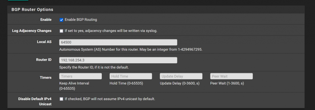
In my setup, I use pfSense as the first AS I consider to use which is 64500. Then I give it a router ID which is the LAN interface.
Then in FRR’s newest version that pfSense uses, it is updated to respect RFC 8212 where bgp routes are not imported/exported unless a policy is applied. For now, to keep it simple, I have a policy which simply accepts all. This is under services > FRR Global > Route Map. Here, I simply created one that is named “Allow-All” and set action to “accept.”
Building First BGP Peer
Under FRR BGP > Neighbor > Add we can now define the first neighbor that we want to establish a IPv4 BGP session with.
If you take a look at my topology diagram from part 1, or the close up picture of the topology below, I use 10.1.100.0/24 for my IPv4 point to point links. Each vlan, which represents a routed link from pfSense to the Nokia router, is a /29. I went to this because I am using two pfSense VMs, and that allows for the 3 CARP addresses needed on pfSense. CARP is a way to have a virtual floating IP – more in another post to come. But this allows a fail over between the pfSense VMs and the Nokia will not need to update any BGP peer, it will simply re-establish if there is a failure.

In any case, for a simple IPv4 eBGP peer, you need 3 things:
- IP address of the neighbor
- ASN (autonomous system number)
- Route Map
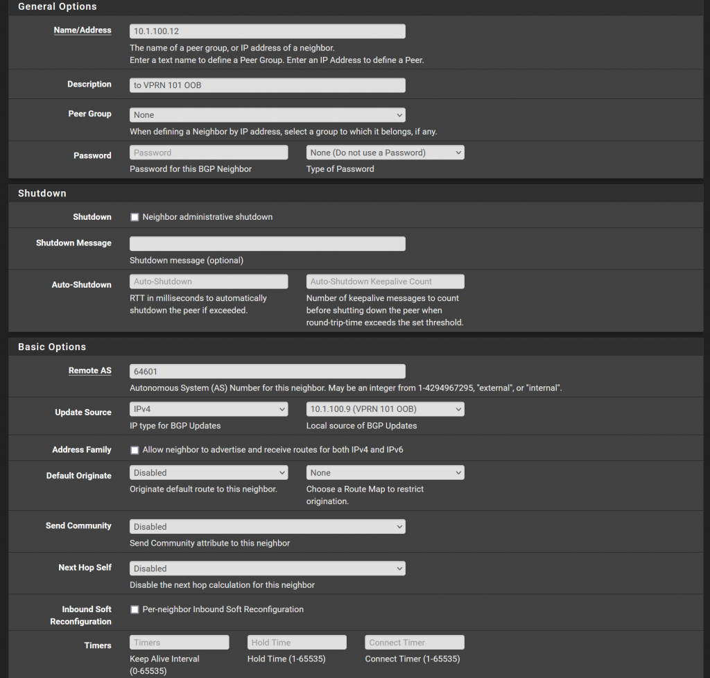
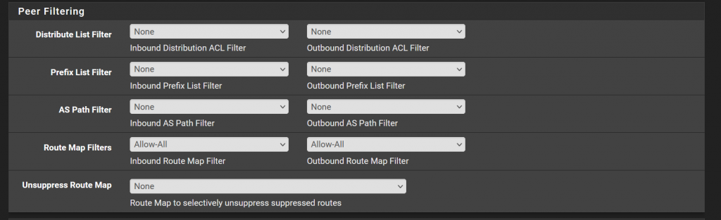
The rest should be able to stay default. There are of course a lot of options in BGP. Not that I want to skip over these, but personally I like to keep pfSense simple. I’m not an expert at FRR and these options in the GUI. I like to create the complexity on the Nokia as I am just more used to it.
Lastly make sure to go to services > FRR Global > and check the “Enable” box to turn the package up.
Building peer on the Nokia router
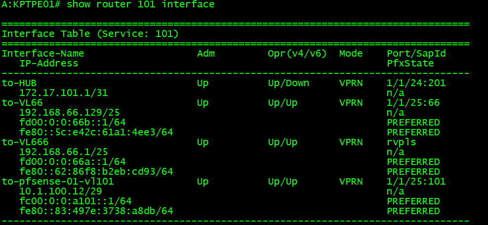
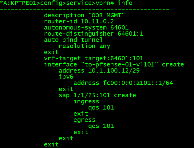
To start out, I simply have printed the interfaces. I have standardized on naming my interfaces “to-pfsense-01-vlxxx” which the vlan corresponds to the VPRN number I use. Notice here, the IPv4 IP is 10.1.100.12 which we defined in pfSense as the neighbor earlier.
For some of the basic parameters, like ASN, router ID, etc. This is defined at the root level of the VPRN service, which is “/configure service vprn 101”
Now I have created a bgp group in the VPRN service. Here I simply defined the neighbor, its ASN, a family, and an export policy.

For completeness, here is the policy:

I wish I could talk about all of this, but I will be skipping a few things to cover later in another blog post. If you already know the other families and extensions of BGP, you probably understand some of the above. To keep this from being a book, I will go over the basics.
Each prefix is in this service, VPRN 101, will be evaluated top down in this policy. So I have several entries that perform drops, accepts, and then finally if a route does not match any of the other entries, the default action is to drop it.
Prefix lists, are just groups of networks. For example the “Routed-Links”
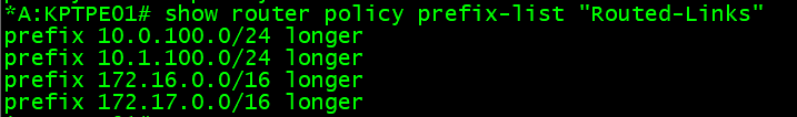
In an effort to try to keep the routing tables clean as possible I, for example, block any of the /29 networks in the 10.1.100.0/24 blockwhich I have set up between pfSense and this Nokia router. The longer just means that anything that falls within the 10.1.100.0/24 range – that has a longer subnet mask, included here. My /29s are longer. I could define every /29 here, but that’s a lot more work, and then every time I would turn up a new VPRN I would have to update policies (which is not ideal).
The main points of interest for this post are the “direct” networks. Direct means any of the layer 3 interfaces that are configured on this router. In my first picture where I looked at the L3 interface, you can see VL66 and VL666. These are direct interfaces, and since I want to be able to have other hosts on my network reach these, and conversely, those networks be able to access other hosts, I am exporting these to pfSense.
Validation
If everything goes right, the peer should be established.
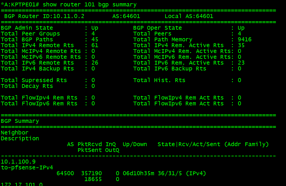
There is a ton of information to digest in this image:
- We can see the BGP information that is local to this VPRN service
- The AS is 64601 (we defined this in pfSense for the neighbor, and local in the Nokia VPRN service)
- BGP is operationally up
- The router ID for this service is 10.11.0.2
- The first neighbor, we can see is the IP of pfSense, 10.1.100.9.
- It has been up for 6+ days (when it is in the up state a addr family will be shown)
- Also we can see that we have received 36 routes, 31 are active in the route table, and 5 are advertised (this is from the heading Rcv/Act/Sent)
- Finally, the address family is IPv4
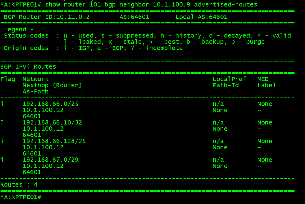
Now let’s looked at received routes, and advertised. This is called the RIB (Routing Information Base) – I cut this down as we do not need to see everything:

Routes that exist in the received RIB, you can think of as a “dumping ground.” Routes are populated here from whatever the peer has sent, but that does not mean that it will be the active route in the route table. An import policy may reject these, and/or other protocols which are advertising the same prefix to this router that may be preferred. If the logic and router determines the route should be installed in the route table because it is best, it will have a status code. Here looking at the static codes u*>i, means that it is used, valid, best, and IGP (mostly just a old carry over when EGP was a protocol before BGP). If we look in the route table we can see the default route exists via the protocol BGP and a next hop of pfSense.

Not forgetting the advertised routes, we can see the two 192.168.66.0 (and 128)/25 networks are there, with a few others which match other accepts in the policies which are being sent to pfSense.
Similarly, we can check pfSense for the information it has. First under Status > FRR. BGP, this will show you the simiar RIB information. Here we can see the two /25s (among others of course) that pfSense learns about from the various eBGP peers.
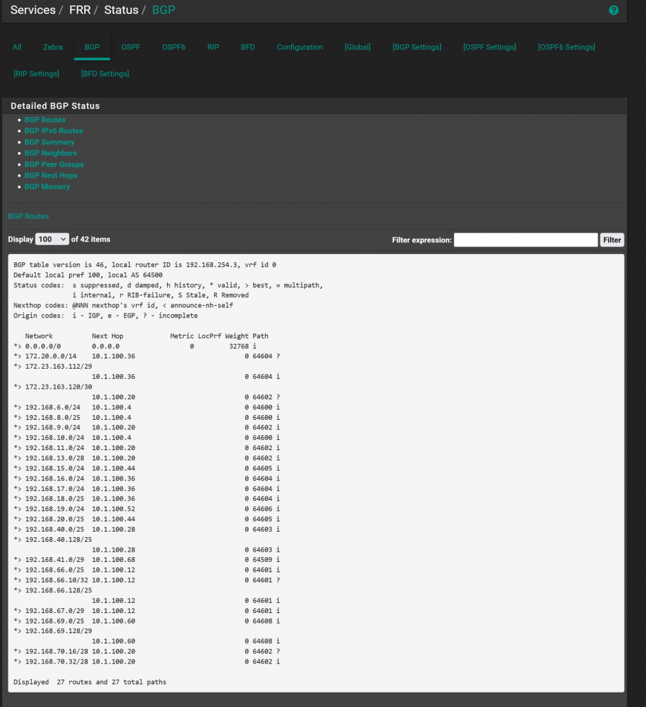
Under status > routes, shows the actual FIB (routing table) in pfSense. Again, we can see the routes are installed, and the RIB gave us that clue they would be as well because the status code is *>

This closes out this part of the discussion. At this point we have a eBGP peer up, and routes are being advertised between the routers. From this point, firewall rules can be assigned to allow/block traffic, and nat rules need to be created to allow the hosts to access the internet since they are private RFC 1918 space. In the next part, I will cover the firewall rules and NAT rules I have applied for this. Eventually, we will get to IPv6, which will be very similar but with a few slight changes.